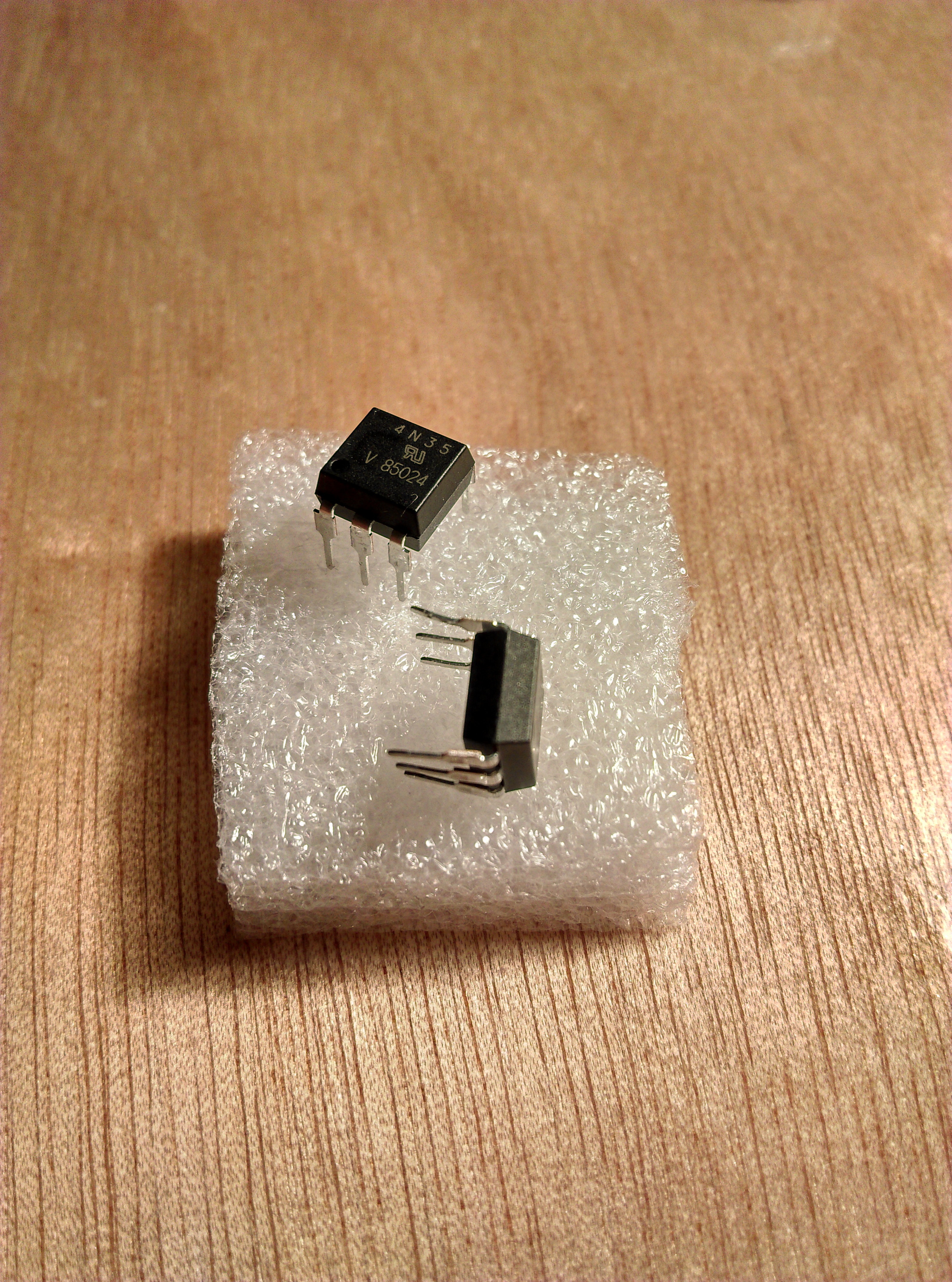
One of the exciting and basic components to start with when picking up electronics as a hobby is the Optocoupler. An optocoupler is an electronic component that converts light into an electric signal. Inside the optocoupler is an LED and a photosensitive device. When turned on, the LED emits light that gets detected by the photosensitive device which in turn emits an electric signal.
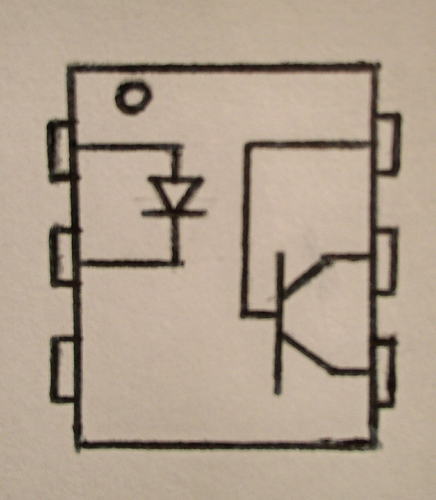
4N35 optocoupler has a tiny circle at the top which helps the user know how to orient it. The schematic below shows that this optocoupler has 6 pins. Inside, we can see the LED and the proximity it has to the photosensor which will be able to convert the light into the electric signal.
To see how an optocoupler works, we use it to connect 2 separated circuits. The first circuit is the one that allows the LED in the optocoupler to actually turn on. The other circuit is on the side of the photosensitive device and it has an LED which allwos us to detect when electricity runs through the circuit.
To build a simple circuit that shows how the optocoupler works we need a breadboard, an LED, 2 resistors (one for the optocoupler and another for the LED), some jumpwires, a switch and the optocoupler itself.
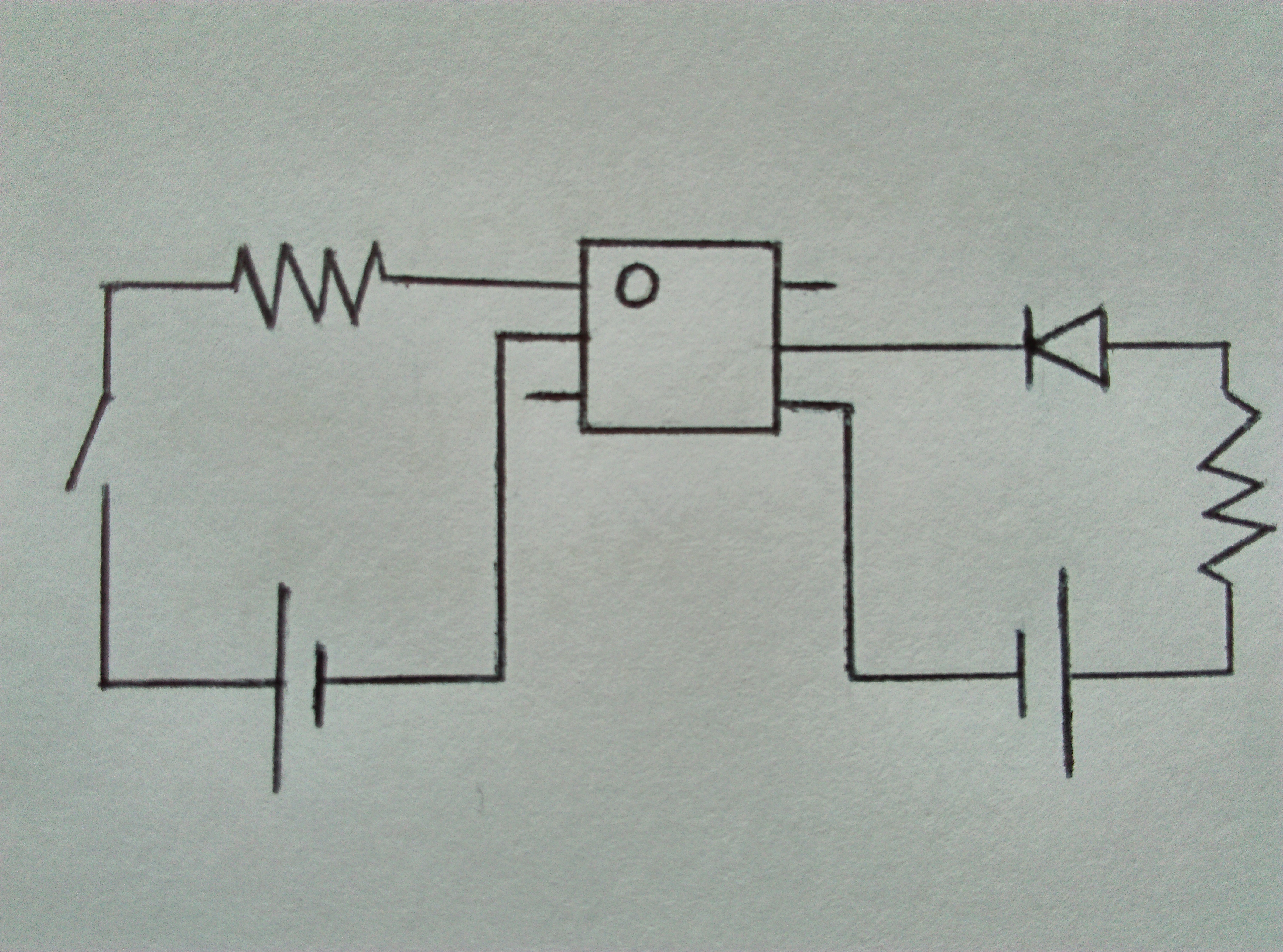
The rough sketch above shows how the components mentioned above are connected to each other. The 4N35 optocoupler sits between 2 circuits. The circuit to the left allows the LED inside the optocoupler to turn on after pressing the switch. The circuit to the right shows the electric signal that flows after the optocoupler's LED is activated. The electric signal created lets the LED to the right side to turn on.
4N35 in a Breadboard Circuit
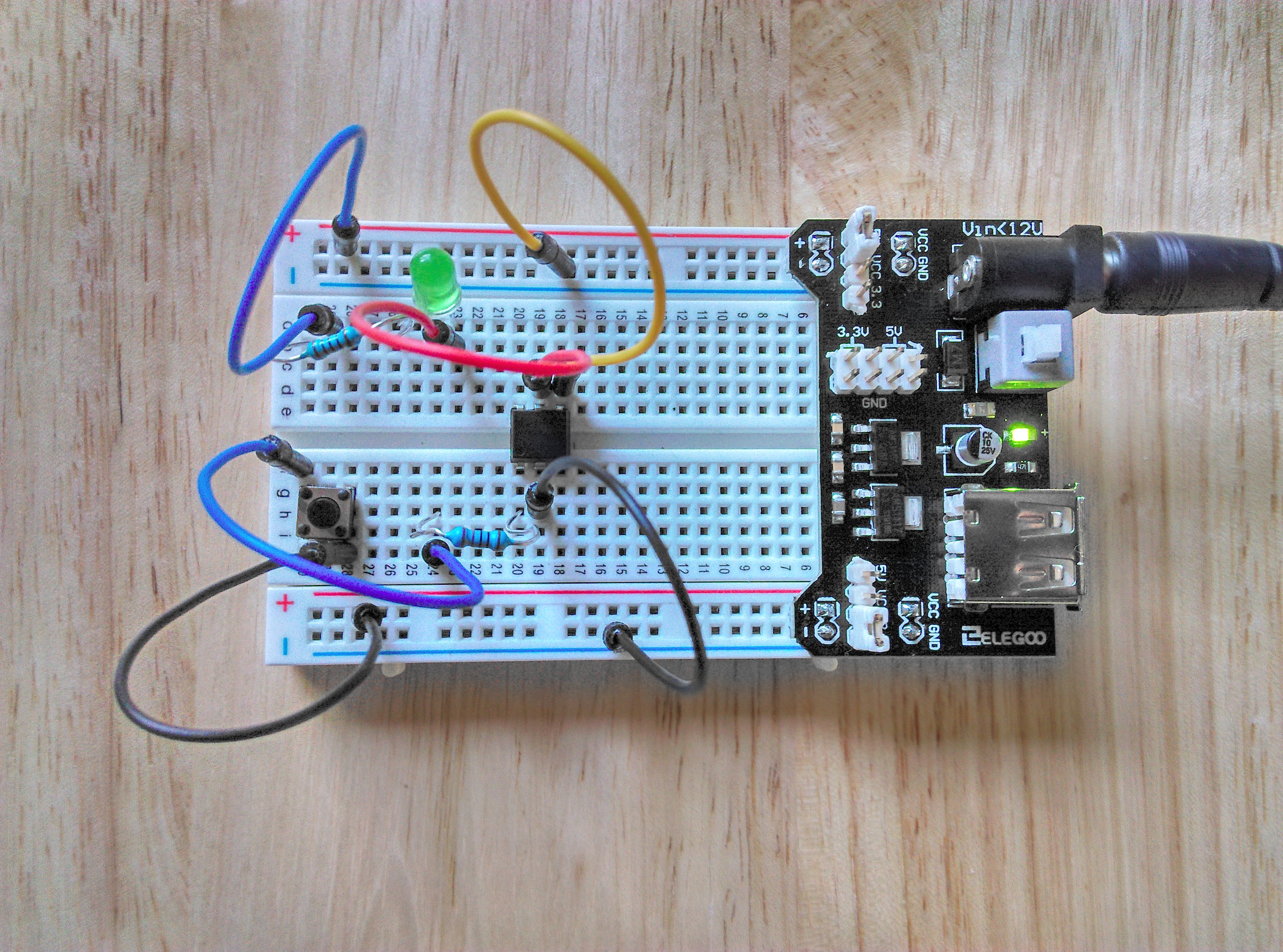
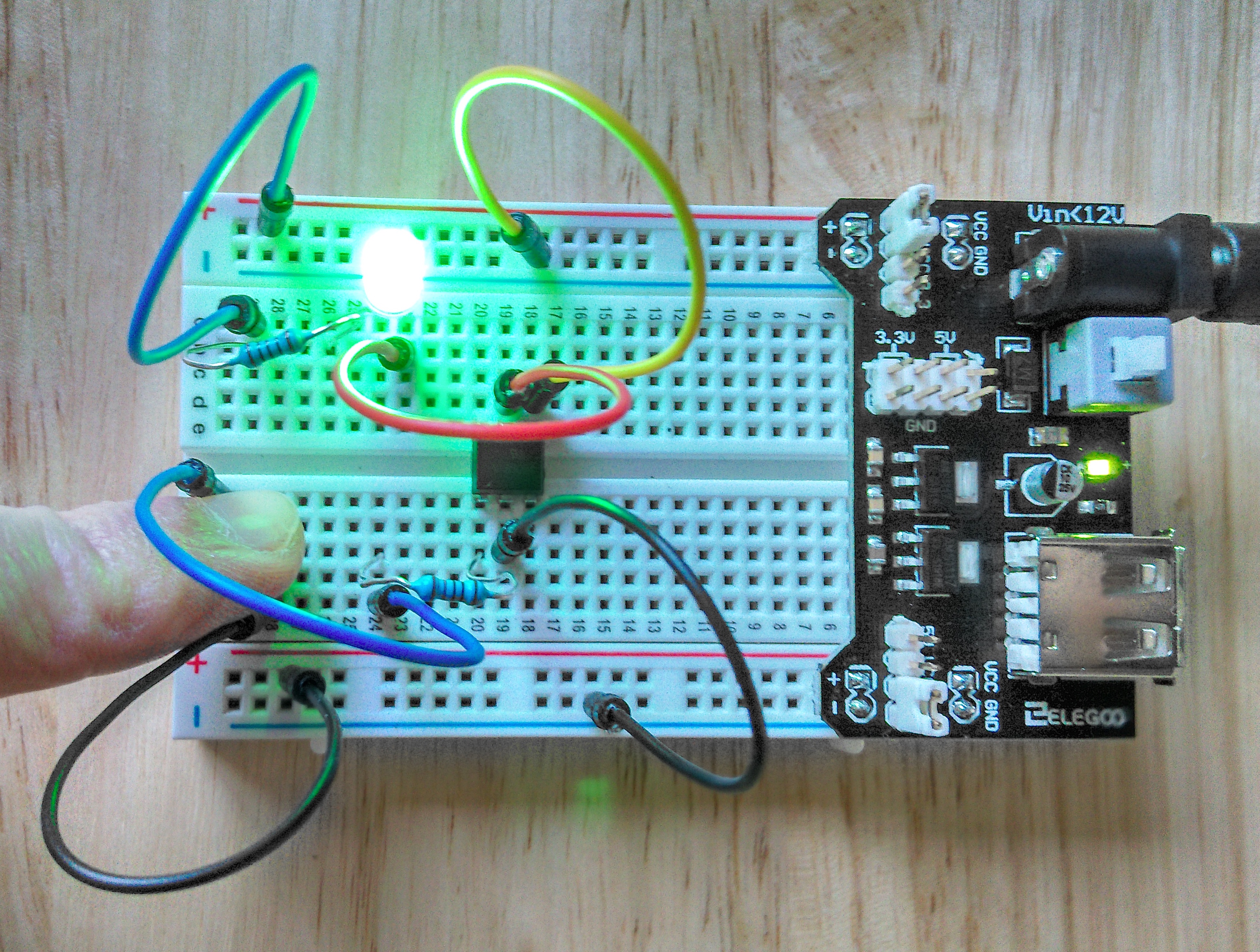
We can now build the schematic onto a real breadboard. In the figures above, the voltage is supplied by the black object on the right of the breadboard which provides DC of 12v.
The figure on the left shows the circuit before pressing the switch. You can see that the voltage is on but the LED is not lit because the switch has not been pressed yet. The figure to the right shows how electricity flows between the 2 isolated circuits after pressing the switch.