If you are like me, as in you need to understand some things that might not be relevant to others then you are in the right place. The macro concept of things is something nice to understand; however, the micro concepts are the things that I find intriguing and that are important when you are trying to understand how something works from inside out.
As I have been using my Elegoo power module to create some basic circuits such as the Optocoupler, I was interested to know what the components on the power module itself were, so I did a bit of exploration. This wasn't straight forward using a simple Google search since the explanations I came across only mostly described the major components on the module which were just 4 out of roughly 20! So here is what I gathered and hopefully you find this useful.
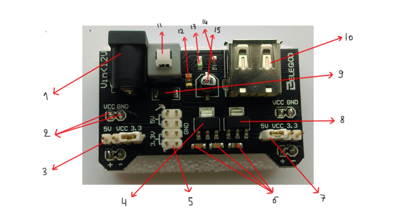
1) Power plug input
This provides a direct current of about 9V via a 5.5mm x 2.1mm plug that goes into the wall outlet. This voltage is reduced by some of the components on the module which I will list below.
2) Vcc and GND pins
Vcc is the voltage common collector that has the higher voltage with respect to the other pin V(GND) or ground. If you look at the module from below, you can see that those are the pins that attach to the breadboard and provide voltage for the protruding header pins.
3) Header
These are 2 4-pin rows that can be insulated using the cap you see in the figure.
4) CJT1117-5
This is a voltage regulator that provides a voltage of 5.0v from an input voltage. This component provides regulated voltage to the adjustable voltage pins.
5) Header
This is a 4-pin dual row which is 2 rows made of 4 pins.
6) Capacitors
3 capacitors of 0.1microF.
7) Header cap
This is a removable cap. It can be used to insulate the pins and halt the current flow.
8) AMS1117-3.3
This is a voltage regulator that provides 3.3v from an input voltage. This component provides regulated voltage to the adjustable voltage pins.
9) M7
This is known as the default diode or rectifier diode. A rectifier is able to convert alternating current (AC) into direct current (DC). The M7 has a V(RRM) repetitive peak reverse voltage of 1000v. This means that while a device can block a maximum value of reverse voltage before it gets damaged, the V(RRM) can block that repeatadly without any damage.
10) USB connector
This provides power to an external device. So you can use this power module to power a device via usb.
11) Power switch
This is a 3-pin dual row switch which means it has a total of 6 pins. It allows the power module to turn on and this is indicated by the LED next to it which turns on.
12) Fuse
Which is a component that protects the circuit from getting injured due to excess current.
13) LED
This LED is used as an indicator for when the power switch is turned on.
14) Resistor
This resistor is labelled as 470R which means 470.0 ohm. A resistor is able to provide resistance for the circuit mostly the LED, which is a sensitive component that burns out under high current.
15) Capacitor
This is a big capacitor of 10 microF.